0xCF53 Remote, Garage Remote
Dr. No Open
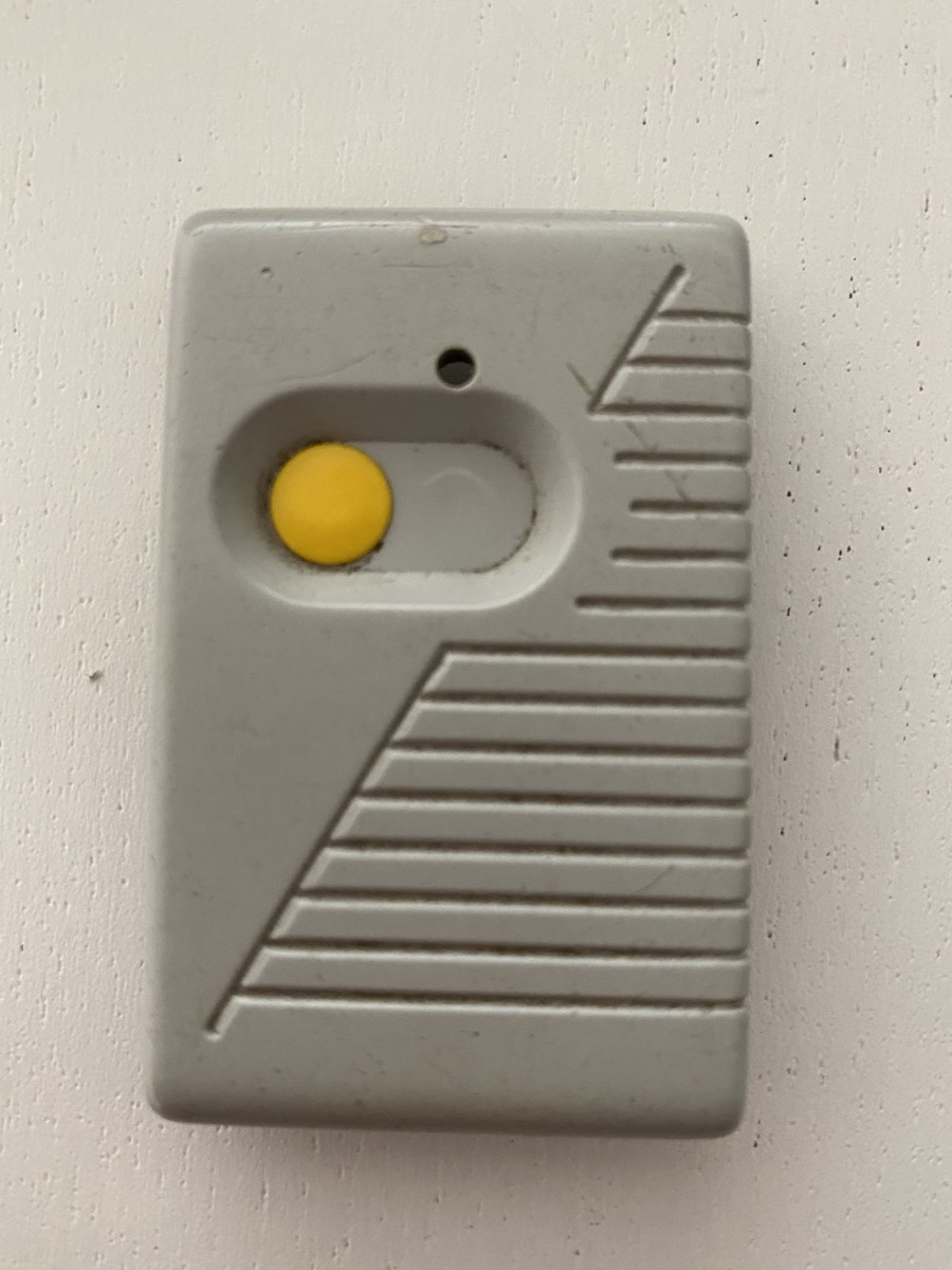
One of my garage openers stopped working but I kept it in hope one day I’d make a learning exercise out of repairing it.
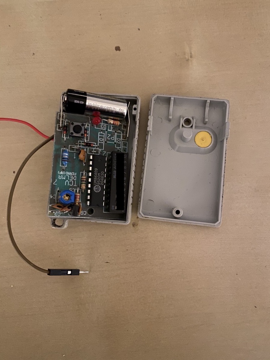
The other day somehow I brought it up in a conversation and it was highlighted that it is common for the push button to wear out, so I opened the case and tested by shorting over the button with a wire.
And the garage door opened (thanks Dad)!
Instead of replacing the push button why not use a raspberry to enable the remote?
Then a webapp could open the garage door?
Alexa, ask Home Assistant to open garage
From StackOverflow With Love
I have used relay switches in the past to open maglocks but the loud clack was annoying and mechanical sounded unnecessary.
Picked up a multimeter and measured at the push button:
- V=10v (opener uses 12v battery)
- I=4mA
Looking into alternatives considered using a simple transistor but sharing GND between the garage opener (12v) and the raspberry (3v3) didn’t sound safe.
Dove into the huge world of ICs (thanks x7!) and, overwhelmed with the options, Google led me exactly to this post in SO. Should’ve started with that…
An octocoupler, LED on one side, transistor with photosensor on the other side. Two isolated circuits, nice one!
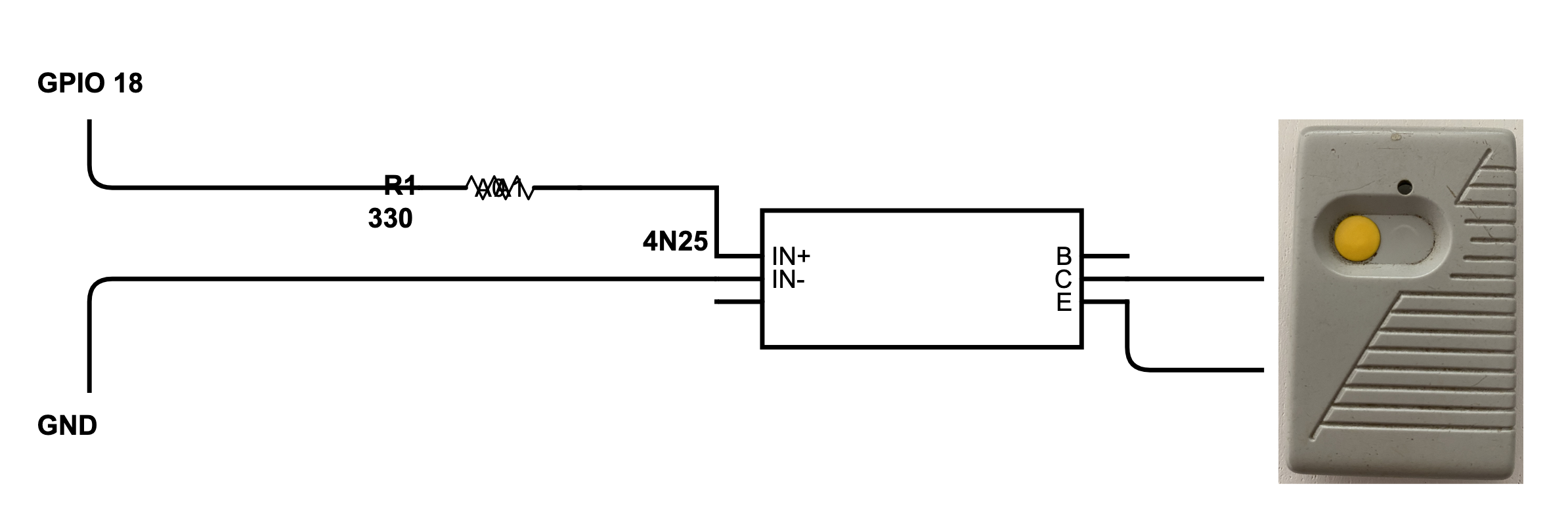
According to this, no more than 16mA should be drawn from an output pin in the GPIO and I had a bunch of 330 ohm resistors:
3v3 = 330 ohm * I>I = 10 mA
Open up 4N25 datasheet: LED on pins 1 and 2 and emitter and collector on 4 and 5.
Schemed it in Digikey, then plugging the bits into a breadboard and connecting to a Pi 0 WiFi:

# shell over python, just for fun
# export pin to userspace
echo "18" > /sys/class/gpio/export
# Sets pin 18 as an output
echo "out" > /sys/class/gpio/gpio18/direction
# "push" the button
echo "1" > /sys/class/gpio/gpio18/value
# for 3 seconds
sleep 3
# release
echo "0" > /sys/class/gpio/gpio18/value
And Sesame is open.
You Must Live Twice
All good and simple, but what about feedback? If the garage opener battery is dead, the Pi cannot see it anywhere…
Let’s use a second GPIO pin as input and enable it with the current from the opener!
But the Pi works on 3v and the opener is working on 10v…
Déjà vu, another 4N25 it is then, the other way around: input will be the garage opener and the output will be connecting Pi 3v3 to the input GPIO pin.
- Updated the scheme in Digikey
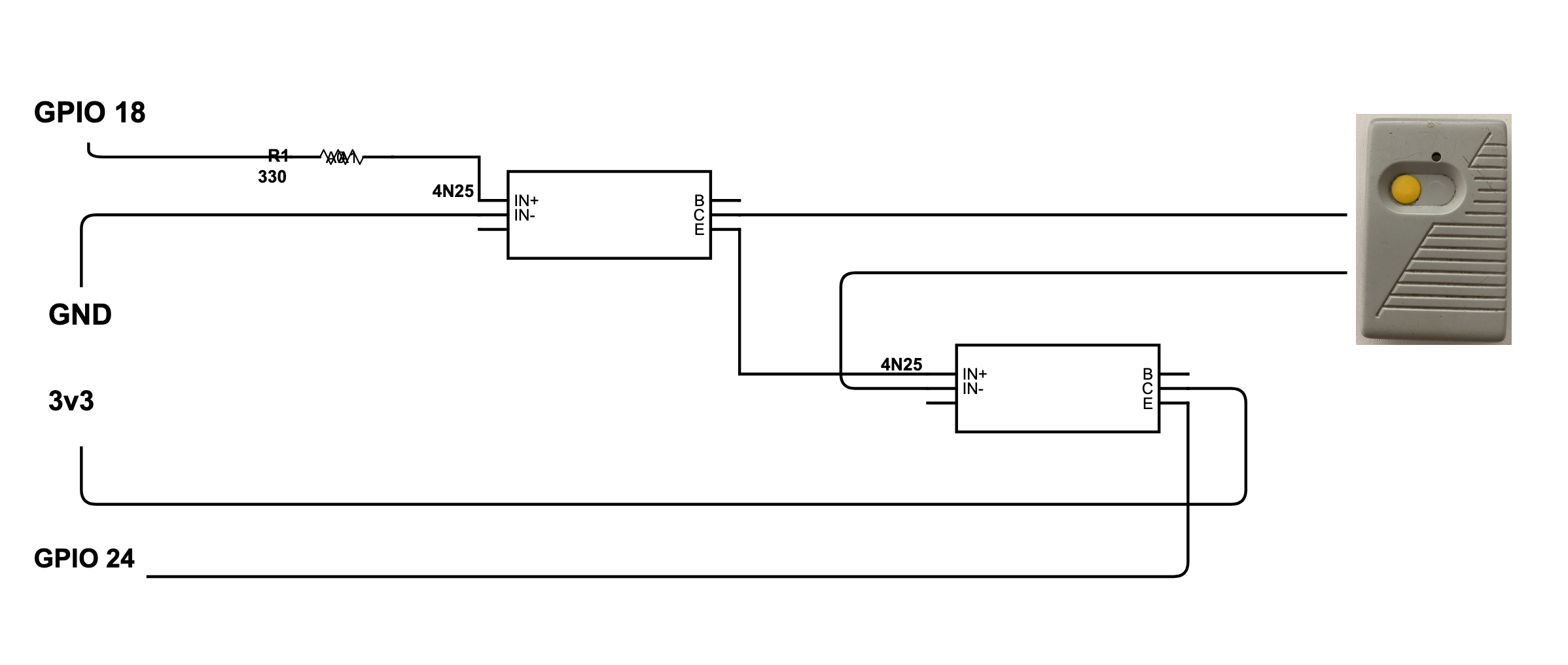
- Applied it in the breadboard

And there: enabling GPIO 18 will enable the opener that then enables GPIO 24. If opener battery is dead, it won’t trigger the second 4N25, not enabling GPIO 24.
In this setup, there’s no GND connected to GPIO 24 so the GPIO setup needs proper pull_up_down:
GPIO.setup(24, GPIO.IN, pull_up_down=GPIO.PUD_DOWN)
Pentapussy
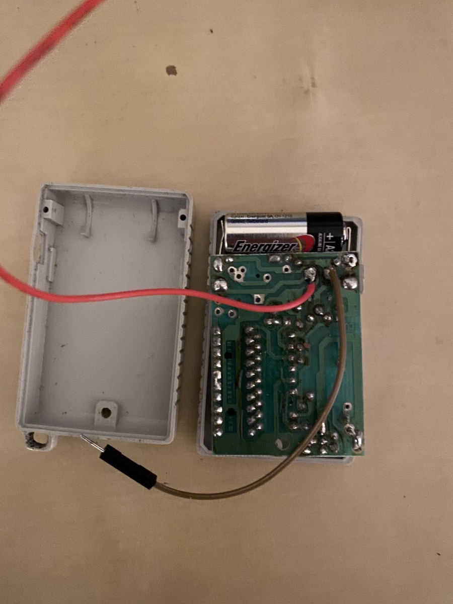
Time to trim a stripboard and solder!

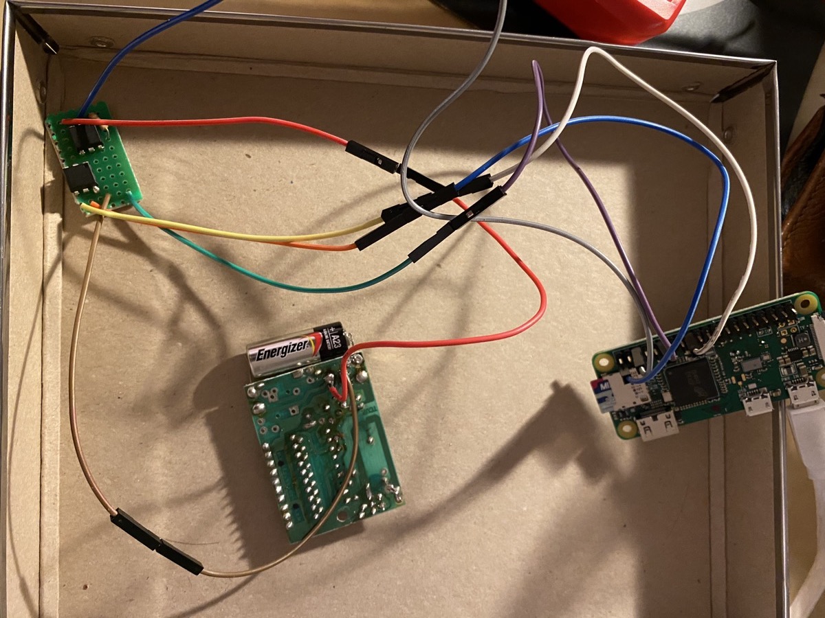
Nice mess of wires but it ended up small
| Wire | Pin |
|---|---|
| Green | Pi GPIO 18 |
| Blue | Pi GND |
| Red | Garage Opener GND |
| Brown | Garage Opener Vcc |
| Orange | Pi 3v3 |
| Yellow | Pi GPIO 24 |
Licence to Click
This wouldn’t be very useful without software to use it.
To change a bit from Python, found a clean Go lib (that uses the sysfs interface) and made a simple one-button webapp rgrweb.

Added some testing flags to use it as a CLI tool. As there is feedback (after adding the second 4N25), it can be used to fully test the circuit wihout actually standing next to the garage door.

The Word is Not Enough
Apologies for using Garage Remote in the title instead of Garage Opener (which I prefer and use in the rest of the text), but IoT pun called for it… Remote Garage Remote…